
A guide by OP Steel
Steel Fabrication Drawings:Types, Uses and Buildability
Guide to steel detailing, shop drawings and steel fabrication drawings, assembly marking, GA drawings and erection information, including how drawing issues affect fabrication and site installation.
- Read time
- 8 min read
- Category
- Detailing · Buildability
- Audience
- For contractors & engineers
What are steel fabrication drawings?
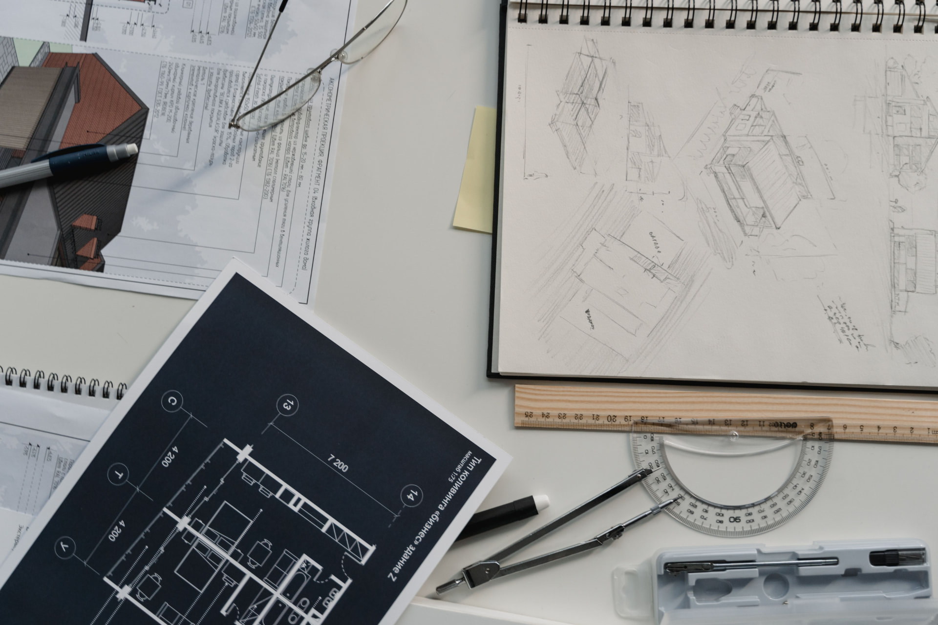
Steel fabrication drawings translate the structural design into the detailed information required to manufacture, assemble and install steelwork. The main drawing types are general arrangement drawings, assembly drawings and single-part drawings.
Drawings must be not only technically accurate, but also buildable, coordinated and suitable for the intended fabrication and installation sequence. That is where good steel detailing and buildability review add value beyond producing a workable set of shop drawings.
The main types of steel fabrication drawings
| Drawing type | Main purpose | Principal users |
|---|---|---|
| General arrangement drawing | Shows the overall steelwork layout and member locations | Project managers, engineers, detailers and site teams |
| Assembly drawing | Shows how several components form one fabricated assembly | Fabricators, welders and quality teams |
| Single-part drawing | Manufacturing information for one individual component | Cutting, drilling and fabrication teams |
| Erection or marking drawing | Identifies where fabricated assemblies are installed | Site supervisors and steel erectors |
What is a general arrangement drawing?
A steelwork GA drawing typically shows:
- Plans, elevations and sections
- Structural grids and setting-out dimensions
- Beam, column and bracing positions
- Member sizes and identification marks
- Levels and key interfaces
- The relationship between different parts of the structure
General arrangement drawings provide the overall project context and are commonly used for coordination, review and erection planning. UK steelwork specifications describe GAs as drawings showing plans, elevations, sections, principal dimensions and erection marks.
GA drawings versus erection drawings
The terms sometimes overlap, but an erection or marking drawing is specifically focused on:
- Assembly marks
- Installation positions
- Grid references
- Levels
- Orientation
- Erection sequence or zones
Drawing conventions vary between contractors, software environments and project specifications, so treat these definitions as typical rather than universal.
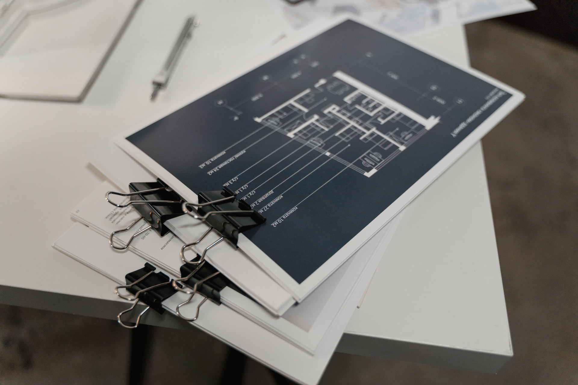
"A coordinated drawing pack is the difference between fabrication that flows and a workshop that waits."
What is an assembly drawing?
An assembly drawing covers one fabricated unit, such as a beam with end plates, stiffeners and cleats. It should normally communicate:
- Main member and attached components
- Part marks
- Hole positions
- Weld locations and requirements
- Dimensions between components
- Material and section information
- Finish or treatment requirements
- Assembly orientation
Assembly drawings are workshop drawings containing the fabrication information for one assembly, normally comprising a main part with secondary parts welded or bolted to it.
Who uses assembly drawings?
Fabricators, welders, inspectors, workshop supervisors and project engineers.
What is a single-part drawing?
A single-part drawing provides the information needed to manufacture one individual component, such as:
- Plate
- Beam
- Column
- Cleat
- Stiffener
- Bracket
- Base plate
Typical information includes:
- Overall dimensions
- Hole sizes and positions
- Cuts, notches and profiles
- Material grade
- Plate thickness
- Part mark
- Quantity
- Relevant tolerances
Single-part drawings are workshop drawings showing the fabrication information for one component, usually without the assembly weld information.
How the different steel drawings work together
- Structural design information is issued.
- The steelwork model and general arrangement drawings are developed.
- Interfaces, dimensions and connections are coordinated.
- Assembly and single-part drawings are produced.
- Components are fabricated.
- Assemblies are delivered and installed using erection information.
- Revisions and site changes are captured and controlled.
- 01Structural design
- 02GA drawings
- 03Assembly drawings
- 04Part drawings
- 05Fabrication
- 06Erection
What is steel assembly marking?
Steel assembly marking is the system used to identify steel members, assemblies and components so the workshop, the delivery team and the site installation team can all understand what each item is and where it belongs in the structure.
Each fabricated assembly is given an assembly mark, and individual components carry part marks. Those marks appear on the fabrication drawings, on the physical steel and on the delivery and erection information.
Clear, consistent assembly marks reduce confusion during fabrication, painting, loading, delivery and erection. Unclear or duplicated marks are one of the most common reasons steel is offloaded in the wrong place, lifted in the wrong order or queried on site.
What is a steel marking plan?
A steel marking plan connects fabricated items to their location in the structure and to the installation sequence. It shows, in plan or elevation, where each assembly mark sits so the site team can locate items quickly without interpreting the full drawing pack.
Poor or unclear marking plans create delays on site, especially where materials are delivered out of sequence, stored in a constrained laydown area, or handled several times before they are installed. On tight urban sites, a good marking plan is often the difference between a smooth lift sequence and a gang waiting while steel is searched for.
GA drawings vs assembly drawings vs erection drawings
The four information sets overlap, but each answers a different question:
| Information set | What it answers |
|---|---|
| GA drawings | The overall arrangement and setting-out information: grids, levels, member positions and how the structure fits together |
| Assembly drawings | How each fabricated item is made up: components, welds, holes, dimensions and finishes |
| Erection drawings | How the steel is installed: positions, orientation, sequence and zones for the site team |
| Marking plans | How items are identified and located during fabrication, delivery and installation |
In short: GA drawings describe the structure, assembly drawings describe the item, erection drawings describe the installation, and marking plans tie the item back to its place in both.
What does buildability mean in steel detailing?
Buildability is whether the steelwork can be fabricated, transported, assembled and installed safely and efficiently – not simply whether it works structurally. A buildability review should consider:
- Whether bolts and welds are accessible
- Fabrication equipment and workshop limitations
- Practical tolerances
- Transport dimensions and weights
- Crane capacity and lifting points
- Temporary stability
- Splice positions
- Installation sequence
- Access for erection teams
- Coating and fire-protection requirements
- Interfaces with concrete, cladding and building services
Design decisions should account for fabrication and erection processes, contractor capabilities and the safe, economical execution of the work.
Buildable drawings only create value if the installation phase is also properly controlled. OP Steel provides installation support for fabricators delivering structural and secondary steelwork packages.
Common drawing and buildability problems
- Bolt locations that cannot be accessed on site
- Welds that cannot be completed in the intended sequence
- Conflicting structural and architectural grids
- Uncoordinated openings or service penetrations
- Assemblies that exceed transport or lifting limits
- Connections that interfere with decking or cladding
- Missing or inconsistent levels
- Excessively tight tolerances
- Late drawing revisions reaching fabrication
- Assembly marks that do not match erection drawings
- Details that are structurally correct but impractical to install
How drawing issues affect site installation
Fabrication drawings are not only a workshop issue. Most of the cost of a drawing problem is felt on site, after the steel has been made and delivered.
Poor drawing coordination typically shows up as:
- Missing information the gang needs to install an item
- Unclear revision status, with more than one drawing pack in circulation
- Incorrect or inconsistent assembly marks between steel, delivery notes and drawings
- RFIs and technical queries raised late and answered slowly
- Rework, remedial holes, site modification and re-lifting
- Access and sequencing problems that were not visible in the workshop
- Installation delays, standing time and disrupted follow-on trades
Each of those becomes a programme and commercial issue for the fabricator, not just a technical one, which is why drawing quality and site control need to be treated as one process.
What fabricators should check before steel goes to site
A short check before delivery prevents most avoidable installation problems:
- Latest revisions issued to site
- Assembly marks clear, legible and consistent
- Erection information available to the gang
- Connection details checked
- Delivery order aligned with the installation sequence
- Secondary steel interfaces reviewed
- Open RFIs and TQs resolved or tracked
- Site team working from the current drawing pack
Steel drawing review checklist for project managers
Before drawings are released
- Are the correct design revisions being used?
- Are grids, datums and levels consistent?
- Have all interfaces been coordinated?
- Are member sizes and material grades confirmed?
- Are connections complete?
- Can bolts and welds be accessed?
- Can assemblies be fabricated using the proposed methods?
- Are lifting, transport and erection constraints understood?
- Are finishes and fire protection coordinated?
- Is the drawing status and approval route clear?
- Are revisions traceable?
Do BIM models replace fabrication drawings?
BIM models improve coordination and can generate linked drawings, schedules and fabrication information, but the required contractual and production deliverables must still be agreed for the project. Modern detailing systems can generate GA, assembly and single-part drawings from the coordinated model while maintaining links between the model and drawings.
Steel connection design and shop drawings
Steel connection design defines how members join – bolts, welds, plates, cleats and end plates – and it must be settled before shop drawings can be finalised. Responsibility for connection design should be agreed early, whether it sits with the structural engineer or is delegated to the fabricator. Late or unclear connection design is a common cause of drawing revisions, fabrication delays and fit-up problems during steel erection.
How buildable drawings protect the project
- Fewer fabrication queries
- Reduced rework
- Better coordination between workshop and site
- More reliable installation sequencing
- Earlier identification of commercial exposure
- Clearer records when changes occur
This reflects OP Steel’s proposition: practical engineering and detailing aligned with site delivery, closing the gap between drawing office and installation.
Frequently asked questions
Need steel drawings that work on site?
OP Steel provides steel detailing, BIM coordination and buildability support aligned with fabrication and installation requirements. Speak to us about reviewing or delivering your next steelwork drawing package.